
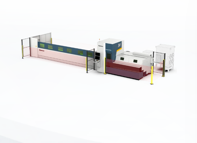
Assessing Automated Material-Loading Failures for High-Power Laser Cutting: A Problem-Driven Protocol
Problem statement and clinical-style objective
Operators report intermittent part misfeeds, inconsistent cut quality, and unexplained throughput drops when an automatic loading cell is placed upstream of a high-power laser cutting line. The objective here is to define a diagnostic protocol that isolates mechanical, thermal, and control-system causes for those failures while assessing whether the upstream automation exacerbates the laser process. Early focus should be on measurable endpoints—feed timing variance, positional error, kerf consistency, and thermal damage to the workpiece—when integrating an industrial-grade high power laser cutting machine.
Case definitions and primary failure modes
Define each failure as you would a clinical syndrome. Syndrome A: transient misalignment—positional error >0.5 mm on more than 2% of cycles. Syndrome B: thermal aberration—localized heat-affected zone (HAZ) thickening beyond baseline material behavior. Syndrome C: control desynchronization—PLC or CNC timing drift causing collisions or doubled feeds. These categories guide which sensors, logs, and physical inspections to prioritize.
Diagnostic protocol: measurements and thresholds
Implement a stepwise examination. Step 1: timestamped event correlation—synchronize the loader PLC, laser CNC, and vision system logs with millisecond resolution. Step 2: mechanical inspection—check spindle and gripper repeatability against manufacturer tolerances. Step 3: optical assessment—measure beam position stability and kerf profile across 50 consecutive cuts. Step 4: thermal mapping—use infrared profiling to detect cumulative heating at fixation points. Set objective thresholds for intervention rather than subjective judgment.
Pathophysiology: how automation interferes with laser process fidelity
Mechanical vibration from rapid loader cycles alters fixturing seating, creating micro-gaps that shift the workpiece during beam engagement. Repeated micro-shocks modify thermal conduction at clamps, raising local HAZ and altering melt dynamics. Control-layer latency—network jitter or buffer overruns—induces asynchrony between clamp confirmation and laser firing. Treat each mechanism distinctly when designing corrective steps.
Mitigation tactics and verification steps
Prioritize controls that reduce root cause probability. Mechanical: increase fixture preload, add compliant seating with defined stiffness, and insert shock absorbers between loader and cutting table. Control: implement handshake confirmations with hard interlocks and extend the confirmation window by defined milliseconds to buffer against network jitter. Optical/thermal: stagger cycle timing to allow heat dissipation, and install a short air-knife or nozzle purge to stabilize melt expulsion. Verify by running a 100-part validation series and report metrics: positional standard deviation, mean kerf width, percentage of parts meeting tolerance.
Alternatives and trade-offs
Evaluate viable alternatives when mitigation is insufficient. Manual loading reduces vibration but increases cycle time and operator exposure. Collaborative robots provide flexibility with lower inertial force but require path smoothing and additional safety validation. Pallet-based automation decouples the laser from the loader at the cost of added capital and space. Each option carries quantifiable trade-offs in throughput, repeatability, and safety that must be compared against defined production targets.
Real-world anchoring and corroborating evidence
Industry demonstrations, such as those routinely staged at the International Manufacturing Technology Show in Chicago, show how integrated automation packages alter cut profiles when not validated as a system. Practical experience from OEM validation teams and published studies on laser–material interaction support the view that automated feeders change boundary conditions for a laser system. Where possible, reproduce demonstrated setups locally and compare to a controlled baseline using a dedicated high power fiber laser cutting machine to quantify delta effects between loaded and unloaded states.
Common diagnostic pitfalls to avoid
Do not presume the laser is the primary problem. Avoid single-point inspections; intermittent faults require synchronized multi-sensor logging. Do not change multiple variables simultaneously—alter one parameter, run a validation series, then document results. Avoid reliance on subjective operator assessment; replace it with objective measurements and error-rate thresholds.
Concluding synthesis and operational recommendation
Apply the protocol iteratively: define the syndrome, measure against thresholds, isolate the mechanism, apply a targeted fix, and verify with a defined validation series. This structured, problem-driven approach converts vague production complaints into actionable engineering tasks and quantifiable outcomes. For systems where integrated validation demonstrates consistent part quality and controlled HAZ, the simplest path to sustained reliability is a validated equipment supplier and a documented validation protocol—a standard embodied in the solutions from Hymson.